
Just a though. Look for the format of the keep alive packet on the k-line. After several seconds of no comms the ECU will assume no connection and drop back to slow baud.
Of you need any pointers on packet structure and response codes let me know.
BTW The theoretical buffer length for k-line transmission is 255 but in practice may be much less.

Results 31 to 45 of 90
-
9th August, 2010, 08:28 PM #31DK Veteran


- Join Date
- Jan 2010
- Location
- Kidderminster
- Posts
- 726
- Thanks

- 1
- Thanks

- 61
- Thanked in
- 38 Posts

-
10th August, 2010, 02:44 PM #32Junior Member
- Join Date
- Jul 2010
- Posts
- 36
- Thanks
- 0
- Thanks
- 10
- Thanked in
- 3 Posts
JimStim MegaSquirt Stimulator with Wheel Simulator - Assembled DIYAutoTune.com
This device may be of interest its cheap simple and effective
I use one of these on my test bench to help with disassembly can simulate crank trigger patterns iac coolant sensors etc.
Good luck
-
13th August, 2010, 12:00 AM #33Member
- Join Date
- Nov 2009
- Posts
- 47
- Thanks
- 0
- Thanks
- 2
- Thanked in
- 2 Posts
Hi guys Originally Posted by MMichael

Thank you very much for all the advise...
I do not think the CAN will influence the working of a test bench at all. For me the purpose of reverse engineering is exactly this, to disable the CAN if it will prevent the test bench setup to start...
I must admit this project is way more difficult than what I thought. When I saw the initial 256k code I thought this could not be diffilcult, get a successful disassembly and read through the code, remember I am used to windows reverse engineering.
Then I started to read the CPU32 instruction set, I started to study the MC68376 documentation and the more I read and study the more I realize how much study it will take to read the code like a book. I still belive it should be easy enough for an experienced embedded programmer to read the code and get to the relevant pieces of code quite easy. For me that knew absloutely nothing about CPU32 before I started this project it is a steep study curve, but everyday that past I know more than the day before so all in all I see progress...
So no, I have not commented a lot of code yet, I started to comment all the initial setup code of the various modules of the CPU chip but have not finished it yet.
I am not at a stage yet where I can comment a piece of code, for instance, look for CAN, do not see CAN and fail to start engine. Of course this will be first price eventually, not disabling the CAN but understanding the code to such a degree.
At the moment it is "priority" to understand the interupt sequence and the way interupts work. I do not think it will make the code read easier as such, for me it is a challenge to understand how the engine gets controlled apart from understanding exactly how the CPU works.
So yes, I saw the sequence of the bytes to reset the watchdog but I do not even know what the watchdog does..;( I have ordered a few books explaining the CPU32 and the 68k family of processors and I hope to learn more from it.
At the same time we are busy to design and build a bench simulator to simulate various functions of the engine. I had a look at the engine simulator but the problem with the one given above is that it is not adequate enough to simulate the S62 engine. Keep in mind the S62 engine use four vanos valves, four CPS sensors, two water temperature sensor, etc etc and various engine components to monitor the working of the engine and if any of this components give a false reading the DME will revert to some or the other safe mapping mode or one of three or is it four limp home modes. Now the challenge is to build a simulator to fool the MSS52 to think it is attached to a fully working engine.
In the mean time work keeps me too busy lately and my progress is slower than what I would like, but like a good friend of mine say, slow and steady wins the race, so onwards I go.
Thanks for all the input, I really appreciate it
Cheers
-
14th August, 2010, 01:17 AM #34Member
- Join Date
- Nov 2009
- Posts
- 47
- Thanks
- 0
- Thanks
- 2
- Thanked in
- 2 Posts
Here is the BIN file that I work with at the moment, please note this is only one CPU file, the other CPU has its own file and controls different parts of the engine.
Use IDA with the Motorolla 68k selected as processor to disassemble.
Cheers
-
15th August, 2010, 09:02 AM #35DK Veteran

- Join Date
- Sep 2009
- Posts
- 1,542
- Thanks
- 14
- Thanks
- 53
- Thanked in
- 47 Posts
A watchdog is a device/chip that checks if the software is working correctly - at least that it has not run-away, crashed or hangs in a indefinite loop. The way it works is you have to kick the watchdog (write the sequence) periodically or it will kick you (perform a hard reset).
BMW has a different approach to communications on the K-line. There's no timeout. Also there's no initialization.
You just ask what you want to know without bothering with initialization or timing.
Also, BMW has 2 versions of the KW2000 protocol. One with 8 bits no parity and 10K4 baud.
The other (older) version has 8-bits WITH parity (I think even, have to check) and 9600 baud.Last edited by oldford; 15th August, 2010 at 09:16 AM.
-
15th August, 2010, 11:14 AM #36DK Veteran

- Join Date
- Jun 2009
- Location
- Bosnia & Herzegovina
- Posts
- 862
- Thanks
- 3
- Thanks
- 331
- Thanked in
- 50 Posts
Also, for BMW's is characteristic XOR check-sum.
Galletto 2012 v54 full with JTAG and Mini available

Big Stars never dies:
Colin McRae (1968 ***8211; 2007)
Richard Burns (1971 ***8211; 2005)
Georg Plasa (1960 - 2011
-
15th August, 2010, 03:11 PM #37DK Veteran


- Join Date
- Aug 2009
- Location
- Netherlands
- Posts
- 857
- Thanks
- 39
- Thanks
- 348
- Thanked in
- 162 Posts
As an CKP and/or Cam signal generator I use a simple funktion generator
feeding an adress counter connected to an Eprom (I use a 2816). Then you can use the 8 data lines as output.
You fill the Eprom with some data to use one of the data lines you want.
In case of the MSS50-54 ecu only the CKP is enough to let it work, but you first have to disable the EWS.
This is in the code where also the fuel data is.
-
15th August, 2010, 05:26 PM #38DK Veteran
- Join Date
- Jan 2010
- Location
- Kidderminster
- Posts
- 726
- Thanks
- 1
- Thanks
- 61
- Thanked in
- 38 Posts
Well that's just sneaky and way off the ISO standard. Originally Posted by oldford
-
15th August, 2010, 06:04 PM #39DK Veteran
- Join Date
- Sep 2009
- Posts
- 1,542
- Thanks
- 14
- Thanks
- 53
- Thanked in
- 47 Posts
Who says you have to comply to ISO standards before 2001? And where does it say a factory protocol has to comply?
And say you have to comply. Who will check that? In Europe they don't even check whether or not a car complies to EOBD.
Look at 2004 and younger diesels. MIL is on, you restart the car, and the code is "forgotten".
And no manufacturer has been fined or sanctioned for infringements like these.
And BMW is not the only one that doesn't comply.
ISO 9141 clearly states how the initialization should be done. It also specifies how many key bytes an ecu is allowed to send back. 2, 4, 6, 8, etc. just along as it's an even number. Why is Fiat using 5 key bytes?
Or a bit more modern - VAG's can protocol. That doesn't match anything published by the ISO or SAE.Last edited by oldford; 15th August, 2010 at 06:37 PM.
-
16th August, 2010, 02:43 AM #40Member
- Join Date
- Nov 2009
- Posts
- 47
- Thanks
- 0
- Thanks
- 2
- Thanked in
- 2 Posts
Is it at all possible to explain in more detail how we can do this please? Originally Posted by easytech
I have bought a 8 way signal generator but found the functionality was not enough to simulate a RPM which can varies and also change four CPS sensors where they should be.
I have read a article where somebody used a C167 to program a simulator but to be honest it will take me another year to learn how to program a simulaotr before I can continue with disassemblig the MSS52 and that is not my idea, hence the reason why we decided to use hardware at the moment.
If you can perhaps help us with the software version of the crankshaft sensor, let us control the RPM and position the four CPS sensors as well via a software signal generator that will be first price..
The DME that I have does have its matching EWS and key so I do not yet have to play with disabling the EWS, that is a project for much later.
Thanks again for all the advise
Cheers
-
16th August, 2010, 10:18 AM #41DK Veteran
- Join Date
- Sep 2009
- Posts
- 1,542
- Thanks
- 14
- Thanks
- 53
- Thanked in
- 47 Posts
How about this idea?
Get a trigger wheel like you have on the car. Connect it to an electric motor of which the rpm can be controlled.
Attach the camshaft trigger wheel with a 50% reduction of the rpm and use the standard sensors?
-
16th August, 2010, 11:11 AM #42Member
- Join Date
- Nov 2009
- Posts
- 47
- Thanks
- 0
- Thanks
- 2
- Thanked in
- 2 Posts
Originally Posted by oldford
That is exactly what we are doing at this stage, but if an electronic simulator is available it would be nice to test.Last edited by Katvis; 30th August, 2010 at 06:44 AM.
-
10th September, 2010, 06:35 PM #43Member
- Join Date
- Nov 2009
- Posts
- 47
- Thanks
- 0
- Thanks
- 2
- Thanked in
- 2 Posts
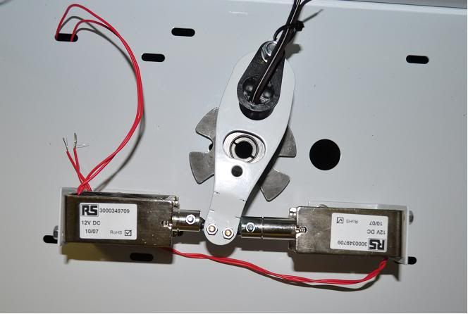
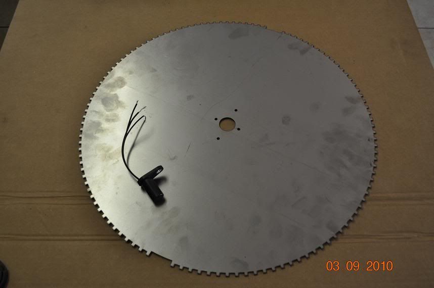
Some pictures from the test bench in construction:
"Vanos" solenoid arrangement
Crankshaft sensor wheel
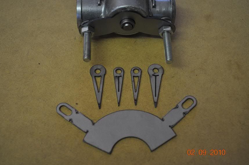
Modified idle control valve with needles for indication:
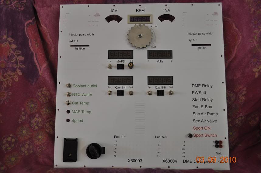
Faceplate, still await missing items in mail:
Rear view of two boxes, sensor wheel runs horizontal in bottom box:
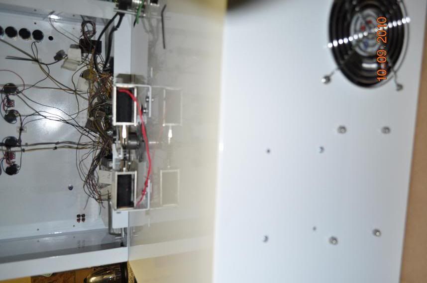
I am still waiting for some spares from the engineering shop and will post more pics once I receive them.
Cheers
-
18th September, 2010, 03:32 PM #44Member
- Join Date
- Nov 2009
- Posts
- 47
- Thanks
- 0
- Thanks
- 2
- Thanked in
- 2 Posts
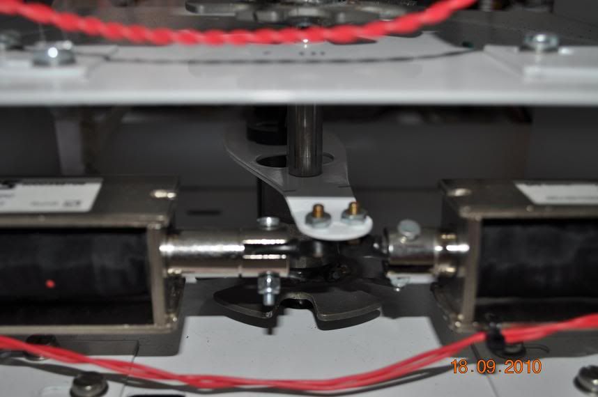
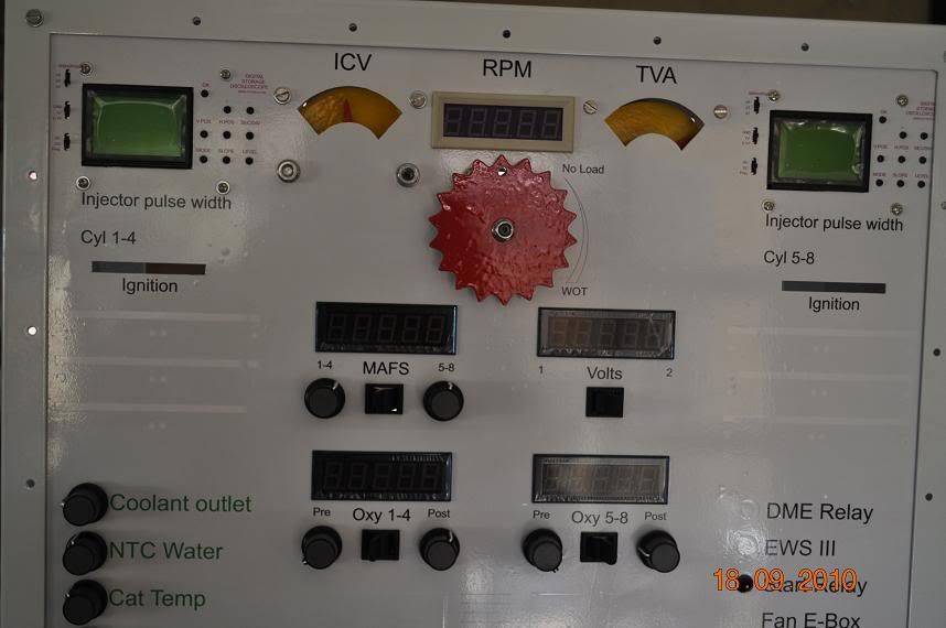
Here are some more pics and update on the working of the simulator:
Picture showing the assembled solenoids with camshaft sensor disc as well as CPS sensor:
Updated picture of the control panel, just a few bits left to go in:
Throttle position sensor, throttle valve actuator plus idle control valve in place:
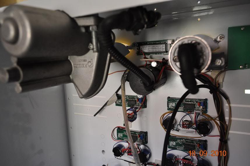
Power supply plus motor speed controller:
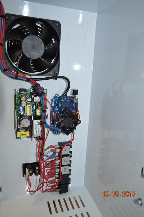
Most of the spares are fitted now, I am still waiting for the three throttle position potentiometers to arrive which will complete the hardware and then I can test the complete workings.
At the moment I can not "start" the "engine" without hot wire. If I hot wire the circuit the motor runs and I can check running parameters. With the propper sensor wheel in place INPA does indicate the correct RPM through the OBD II diagnostic port.
I have setup up the timing of the camshaft discs as well by using DIS display of the camshaft positions, if I manually control the solenoids I can even simulate a successful vanos test..
There are still a few error codes at the moment, mostly the CAN bus errors and then the oil level sensor. I have a oil level sensor connected but the WDS explanation is that the oil level is just looped through the DME but the main feed is to the IKE.
My main concern at the moment is that I thought I will go into the code and trace the CAN bus routines and try and make the CAN believe that it saw the missing modules. First problem is that there are no CAN setup in the code...
I have both CPU chips BIN files and not in one of the BIN files is there any setup routines for the CAN bus. Next I traced the pins for CAN back to the PC board. I could get the CAN chip plus a second "82527 SERIAL COMMUNICATIONS CONTROLLER, CONTROLLER AREA NETWORK PROTOCOL" chip. This chip is connected to the CPU via address lines but there are no connections to the CAN TX and RX lines on the CPU chip.
Next I tried to trace the TX and RX lines of the two CAN lines from the CPU. I could not find any place that they connected to. The pins does have pc tracks on them but they appear not to connect to any components on the PC board? This is a bit confusing for me unless all the CAN bus routines are done through the above two chips?
Next I will try and trace the code where the CS lines are connected to the CPU and see when the chip is selected and try and figure out how the CAN is controlled.
CheersLast edited by Katvis; 19th September, 2010 at 06:41 AM.
-
18th September, 2010, 10:29 PM #45DK Veteran
- Join Date
- Jan 2010
- Location
- Kidderminster
- Posts
- 726
- Thanks
- 1
- Thanks
- 61
- Thanked in
- 38 Posts
Is it a multi layered circuit board?
It does not matter how slowly you go so long as you do not stop - Confucious
You will move very slowly when facing a brick wall - Alexics
Ford Visteon V series LOCKED - SORTED
Ford Visteon V series CODE OFF - SORTED
Ford Visteon V series recoding - IN PROGRESS
Ford Visteon V series calculator - IN PROGRESS
VW Blaupunkt calculator - IN PROGRESS

 Reply With Quote
Bookmarks