
Im looking for Oscilloscope for checking CAN lines. Also with the ability to have a saved known good graph to compare to the can waveform thats being read.

Results 1 to 8 of 8
-
27th August, 2018, 04:02 AM #1DK Veteran


- Join Date
- Jul 2016
- Location
- USA
- Posts
- 1,342
- Thanks

- 770
- Thanks

- 88
- Thanked in
- 76 Posts
 Need Oscilloscope and help for checking CAN
-
27th August, 2018, 05:42 AM #2Top Poster
- Join Date
- Jan 2012
- Location
- EU
- Posts
- 123
- Thanks
- 14
- Thanks
- 39
- Thanked in
- 35 Posts
If you want to study/test CAN lines, better to have also CAN analyzer. Originally Posted by borshch

With it, you can see is bus alive, and what messages are transmitted.
You can also generate your own CAN messages with CAN analyzer.
-
The Following User Says Thank You to Aajii For This Useful Post:
borshch (27th August, 2018)
-
27th August, 2018, 05:51 AM #3DK Veteran
- Join Date
- Jul 2016
- Location
- USA
- Posts
- 1,342
- Thanks
- 770
- Thanks
- 88
- Thanked in
- 76 Posts
I’m looking for a type that I can check can lines on a vehicle for example: if there is corrosion on can wires or intermittent signal or faulty module messing up a can network etc
-
27th August, 2018, 09:04 AM #4Top Poster
- Join Date
- Jan 2012
- Location
- EU
- Posts
- 123
- Thanks
- 14
- Thanks
- 39
- Thanked in
- 35 Posts
One basic measurement is with multimeter:
CANbus voltages (canh/canl) are approx. 2.5V measured betweem CAN - GND with multimeter.
Normally voltage should be between 2.0 V - 4.0 V.
If it is lower than 2.0 V or higher than 4.0 V, it is possible that one or more nodes have faulty transceivers.
If you want to measure with oscilloscope, electronic oscilloscope is good.
My opinion is that Rigol scopes has good price/qualityLast edited by Aajii; 27th August, 2018 at 10:24 AM.
-
The Following User Says Thank You to Aajii For This Useful Post:
borshch (27th August, 2018)
-
27th August, 2018, 01:41 PM #5Top Poster


- Join Date
- Nov 2015
- Posts
- 109
- Thanks
- 14
- Thanks
- 12
- Thanked in
- 12 Posts
Actually, you need no example charts of can bus, since they are very clear and simple.
It must be something like this:
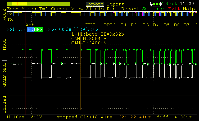
The "data" is difference between CAN-H and CAN-L signals, which must be about 2.5V"thanks" if i helped you is really appreciated
-
The Following User Says Thank You to gljuk For This Useful Post:
borshch (28th August, 2018)
-
28th August, 2018, 01:25 AM #6DK Veteran
- Join Date
- Jan 2014
- Posts
- 673
- Thanks
- 327
- Thanks
- 35
- Thanked in
- 23 Posts
PICO SCOPE is what u should read about
-
The Following User Says Thank You to Mr Mo For This Useful Post:
borshch (28th August, 2018)
-
28th August, 2018, 01:31 AM #7DK Veteran
- Join Date
- Jul 2016
- Location
- USA
- Posts
- 1,342
- Thanks
- 770
- Thanks
- 88
- Thanked in
- 76 Posts
Whats the minimum bandwidth MHZ for a scope for can data analysis ?
-
28th August, 2018, 01:36 AM #8V.I.P. Member

- Join Date
- Mar 2015
- Location
- Canada
- Posts
- 7,965
- Thanks
- 1,280
- Thanks
- 8,324
- Thanked in
- 5,282 Posts
Any automotive scope is adequate, but like previously stated you can do it with a meter.
You won't be able to decipher any detail in a CAN signal, just verify the operating voltages.
First you need to know what system you are working on, UART, hi speed or lo speed CAN, PCI Bus, CCD Bus, one wire, two wire, they are all different.
I repaired a Caravan no start dead dash CCD Bus problem with just a meter, the process is the same for all, disconnect modules till the bus goes normal.
In my case, CCD Bus was 2.5V key OFF with the door open and BCM awake to control the interior lights, key ON it was 9V Turns out the HVAC panel had a cold solder joint on the ground pin, which caused the module to seek a ground through the CCD Bus taking down the whole van.
Last edited by clusters; 28th August, 2018 at 01:38 AM.
Please DO NOT PM me asking for help.
Post in the forum, that is what it is here for.
-

 Reply With Quote
 Posting Permissions
All times are GMT +1. The time now is 05:20 AM.
 Cookie law compliance provided by
Cookie Control v1.0.0 Patch Level 1 (Lite) -
vBulletin Mods & Addons Copyright © 2025 DragonByte Technologies Ltd.
Cookie law compliance provided by
Cookie Control v1.0.0 Patch Level 1 (Lite) -
vBulletin Mods & Addons Copyright © 2025 DragonByte Technologies Ltd.
vBulletin Optimisation provided by vB Optimise (Pro) - vBulletin Mods & Addons Copyright © 2025 DragonByte Technologies Ltd.
Digital Kaos does not condone any illegal operations, including obtaining premium tv for free. Digital Kaos does not accept responsibilty for the loss of any equipment used.
Everything discussed on this forum is for experimental and educational purposes only. Use the information at your own risk.
vBulletin Skin By: PurevB.com
Powered by vBulletin® Version 4.2.5
Copyright ©2000 - 2025, Jelsoft Enterprises Ltd.
Copyright ©2000 - 2025, Jelsoft Enterprises Ltd.
vBulletin Optimisation provided by vB Optimise (Pro) - vBulletin Mods & Addons Copyright © 2025 DragonByte Technologies Ltd.
Digital Kaos does not condone any illegal operations, including obtaining premium tv for free. Digital Kaos does not accept responsibilty for the loss of any equipment used.
Everything discussed on this forum is for experimental and educational purposes only. Use the information at your own risk.
Bookmarks